
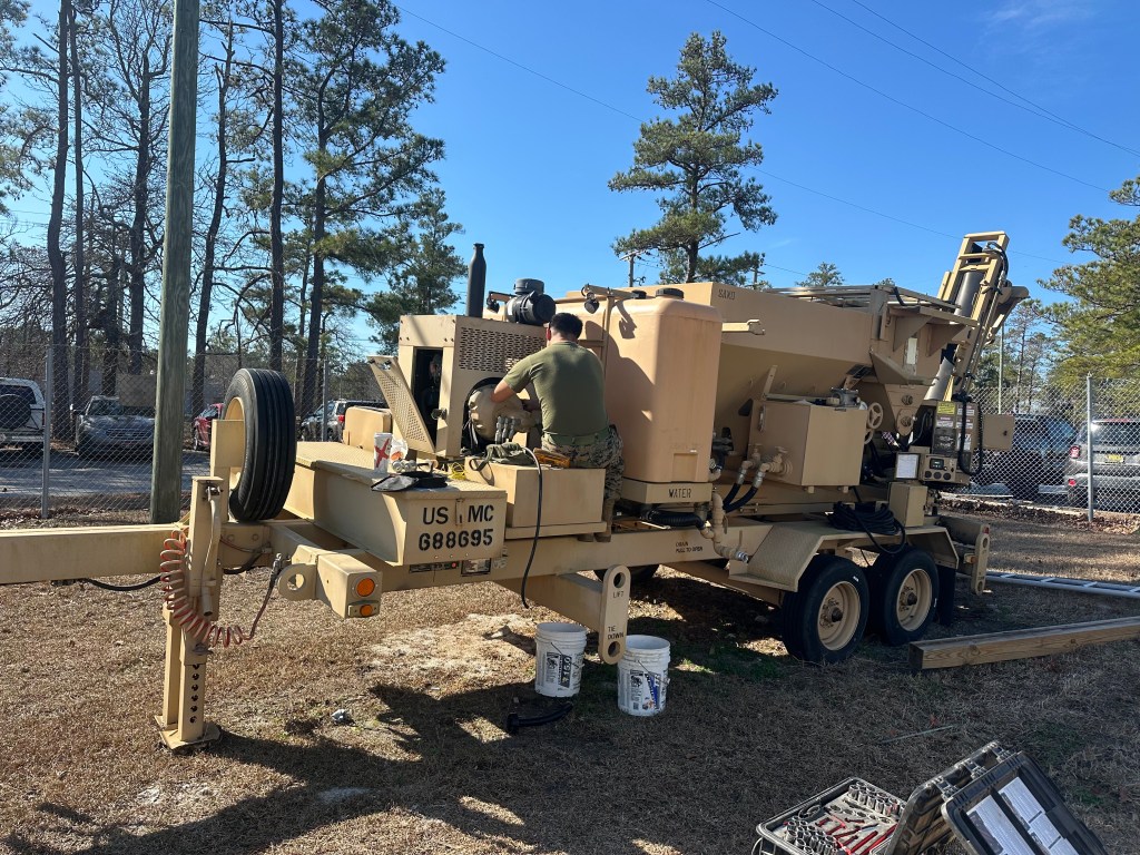
Concrete Mixer Repaired On‑Site – Full Electrical and Fuel Diagnosis
Problems Identified and Solved:
❌ Machine wouldn’t start
❌ Sand vibrators not working
❌ Stone vibrator not working
🔍 Main Issue – Machine Wouldn’t Start
I confirmed that the engine was cranking, indicating the starter was functioning.
I tested the battery voltage: 24V, which ruled out both the starter and battery.
I disconnected the fuel hose and found no suction during crank — indicating a fuel delivery issue.
I tested the fuel pump relay and found 350 ohms between pins 85 and 86 (acceptable), and confirmed there was continuity between pins 30 and 87a, as expected when the relay is not energized.
I heard the relay click when cranking and confirmed with a multimeter that 22V was reaching the fuel pump.
➡️ Diagnosis: Faulty fuel pump
➡️ Solution: Replaced fuel pump → Machine started successfully
⚠️ Secondary Issue – Vibrators Not Working
After the mixer started, I noticed:
✅ Concrete vibrator working
❌ Sand vibrator 1 not working
❌ Sand vibrator 2 not working
❌ Stone vibrator not working
The mixer used 4 relays for vibration:
Concrete vibrator (working)
Sand vibrator 1
Sand vibrator 2
Stone vibrator
🛠️ Troubleshooting Process
I verified that all fuses were good and 24V power was reaching each relay input (pin 30).
I removed the working relay from position 1 (concrete) and installed it in position 2 (sand 1) → The vibrator worked.
➤ Diagnosis: Relay 2 faulty
I moved the same good relay to position 3 (sand 2) → No change.
I traced the wiring to the vibrator and confirmed 24V was present.
I swapped the connections between sand vibrators 1 and 2 → Sand vibrator 1 worked.
➤ Diagnosis: Sand vibrator 2 was defective
Finally, I installed the good relay in position 4 (stone) → The stone vibrator worked.
➤ Diagnosis: Relay 4 faulty
✅ Final Repairs Summary
🔄 Replaced fuel pump
🔄 Replaced 2 faulty relays (Sand 1 & Stone)
🔄 Replaced 1 defective vibrator (Sand 2)
After all components were replaced and tested, the equipment was fully operational again.
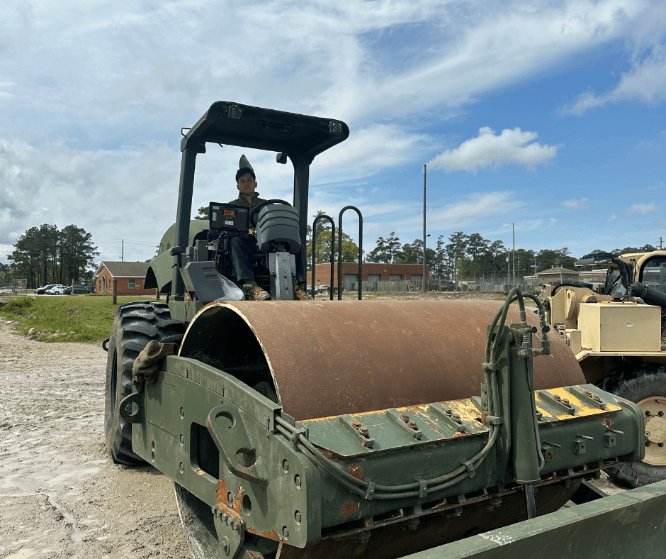
🔧 Equipment Repaired: Compactor
📍 Full diagnostic and multi-system repair
Problems Identified and Solved:
• ❌ Engine would not start
• ❌ Vibration system not working
• ❌ VPM gauge not working
• ❌ Vibration stuck at 2000 VPM
🔋 Electrical System & Starting Issue
• I found one completely dead battery, and after charging, it only reached 320 CCA — confirming it needed replacement.
• I conducted a bench test on the starter, which failed, so I replaced it as well.
• After replacing the battery, the equipment still only started when slaved. That led me to discover a mistake I had made:
➤ I had connected the starter only to the slave cable, leaving the battery’s positive cable disconnected.
➤ Once I properly connected both positive cables, the machine started independently.
✅ Solution: Replaced battery and starter, corrected wiring mistake
⚙️ Vibration System Not Activating
• The vibration system wasn’t responding to the switch.
• I traced the circuit and discovered the issue was mechanical: a click-style contact was not closing properly to signal the ECM.
• The metal tab inside the mechanism was sitting too high, so no contact was made and the ECM never received the vibration command.
• I adjusted the contact mechanism so the click would register and send the signal properly.
✅ Solution: Adjusted mechanical click mechanism to restore signal to ECM
📊 VPM Gauge Not Working
• The VPM display was blank.
• Using a multimeter, I found no continuity in the yellow signal wire between the sensor and its connector.
➤ The wire was internally broken.
• I replaced the damaged wire and verified signal flow.
✅ Solution: Repaired yellow signal wire → Gauge working correctly
🛠️ VPM Regulation Failure
• The vibration system was active, but it was stuck at 2000 VPM, with no way to adjust.
• I initially suspected the rheostat, and testing showed infinite resistance — the internal arm was not making contact with the resistance track.
• But I also discovered that the rheostat had been miswired, bypassing the controller completely.
• I reconnected the rheostat to the controller and then welded the internal contact arm to ensure it would touch the resistance track.
• The rheostat has three wires:
• A center (common)
• Two feedback wires on each side
➤ When the arm moves toward one side, resistance between it and the center drops to 2 ohms or less.
➤ Moving toward the other side, resistance increases to ~900 ohms.
➤ This allows the system to regulate the vibration speed properly.
✅ Solution: Rewired rheostat to controller and welded internal contact → VPM now adjusts correctly (1500–2000 VPM)
⸻
✅ Final Repairs Summary
• 🔄 Replaced battery (320 CCA after charge)
• 🔄 Replaced faulty starter after bench test
• 🔄 Fixed wiring mistake
• 🔄 Adjusted click mechanism for ECM signal
• 🔄 Repaired yellow wire to VPM gauge
• 🔄 Rewired and welded rheostat internal contact
• ✅ Machine now fully functional across all systems
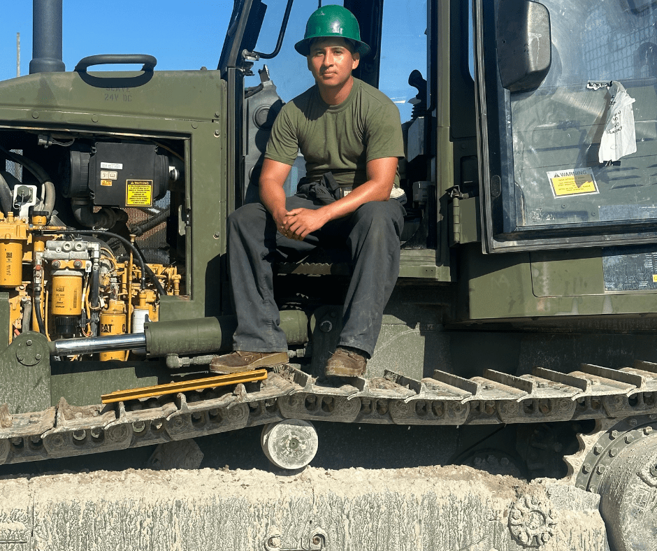
🚜 Equipment Repaired: Caterpillar D6K – Total Electrical Failure
📍 No power – full electrical diagnostic and root cause identified
Symptoms Reported:
❌ Machine randomly shut down during operation
❌ Eventually would not start at all — not even in auxiliary mode
❌ Complete loss of electrical power
🧪 Initial Troubleshooting
My first step was to check the batteries — voltage was fine.
I inspected key fuses and switches, including the keyless switch, and even swapped it with a known-good unit as a test — no improvement.
I then moved to the breaker 105 (main breaker) — it was still in position, but no power was passing through.
Checked the main relay wiring — found no energizing voltage reaching it.
🔍 Systematic Voltage Tracing
Since no obvious faults appeared at the relays or breakers, I decided to trace the voltage path step by step:
1️⃣ Battery Negative Terminal:
Voltage test: 24V confirmed
Routed to Battery Switch, then to ground
2️⃣ Battery Positive Terminal:
Voltage test: 24V confirmed
Routed to:
Junction Block
Junction 1
Breaker 105
Main Relay
Remaining system components
At Breaker 105, I found:
24V present on one side
Zero volts on the output side — power was not passing through.
✅ Diagnosis: Breaker 105 was internally faulty, despite appearing visually fine.
🔧 Repairs Completed
I replaced Breaker 105.
After replacement, 24V was present on both sides of the breaker.
The main relay energized properly, and the entire machine powered up normally.
🧭 Root Cause Found: Secondary Issue
After restoring power, I investigated why the breaker failed in the first place. That’s when I discovered:
The negative terminal cable at the battery switch was loose.
It had been intermittently shorting against the frame — signs of melted metal were visible.
This intermittent short likely caused voltage spikes, leading to the breaker’s internal failure.
✅ Solution: I also replaced the negative battery cable to prevent future issues.
Diagram
Battery (-) ➔ Battery Switch ➔ Ground
Battery (+) ➔ Junction Block ➔ Junction 1 ➔ Breaker 105 ➔ Main Relay ➔ ……..
✅ Final Results
🔧 Diagnosed total power loss step-by-step
🔧 Identified faulty breaker 105
🔧 Replaced breaker and restored full electrical function
🔧 Discovered root cause: loose ground cable causing intermittent short
🔧 Replaced damaged negative battery cable
✅ Machine fully operational
Many electrical failures are hidden inside simple components. Visual inspection isn’t enough — trace voltage point by point. Also: always search for why a part failed, not just replace it.
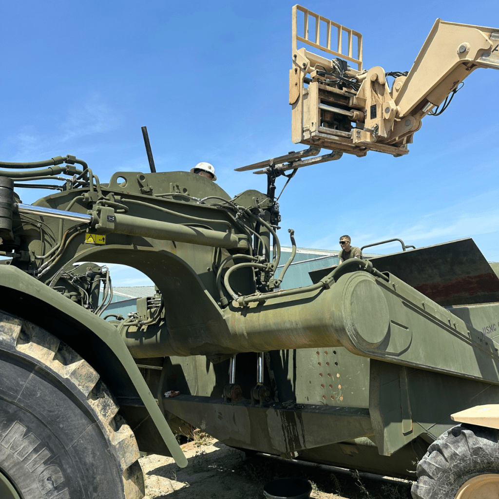
🚜 Equipment Repaired: Scraper – Hydraulic Cylinder Rebuild
📍 Teamwork, safety, and precision mechanical repair
Problem Identified:
❌ Hydraulic leak detected on scraper cylinder
❌ Internal seal failure found during inspection
🛠️ Cylinder Removal: Teamwork First
The cylinder was located in a tight, difficult position.
We worked as a 4-person team to ensure safe removal.
Used a 5K forklift for controlled lifting and support.
A platform was set up to safely access and remove the pins, which were very tight.
Coordinated removal avoided injuries and protected surrounding components.
🔧 Cylinder Disassembly
The cylinder was secured on the ground for rebuild.
We removed the bolts using an impact drill, making disassembly easier than some previous cylinders we’ve worked on.
Once the bolts were out, separating the cylinder was straightforward.
As usual, we prepared a drip pan for fluid collection, but like often happens on real jobs, some hydraulic oil still managed to spill — right onto my foot this time.
➔ Part of the job sometimes.
🔬 Inspection and Repair
Inspection revealed one of the rubber seals was already broken — likely the cause of the leak.
Regardless, we routinely replace all rubber seals, O-rings, and serviceable components inside every cylinder during a rebuild.
No mechanical (metallic) components required replacement.
🏗️ Reinstallation
Once fully rebuilt, we carefully lifted the cylinder back into position with the forklift and full team coordination.
Pins were reinstalled with proper alignment.
Final system tests confirmed full function and no leaks.
✅ Machine returned to full operation.
🚜 Equipment Serviced: Caterpillar D6K – Sensor & Hose Replacement + Functional Validation
📍 Sensor troubleshooting, CAT ET diagnostics & final prep for inspection
⸻
🧰 Assigned Task:
I was in charge of replacing three parts and ensuring the machine was fully operational for final inspection:
• ✅ A hose connecting the fuel-water separator to the next filter
• ✅ A brake pedal position sensor
• ✅ A left motor speed sensor
Before installation, I connected CAT ET and found:
• ⚠️ Code: 8V DC voltage supply above normal
• ⚠️ Code: Brake pedal fault
After replacing the parts, I powered on the machine — everything seemed fine…
…until I saw a fuel leak, but this time it wasn’t at the hose connections.
🔍 The leak was coming from within the fuel-water separator itself, between the filter and the water trap — a two-piece unit that had failed internally.
➡️ I replaced the entire assembly, solving the issue.
⸻
⚠️ Unexpected Alert After Startup:
Once running with no codes, I tried to move the equipment — and it suddenly stopped with an alert. Movement was locked. Clearly a safety function had been triggered.
Using CAT ET, I checked motor data:
• When moving forward:
• 🟢 Right motor: Positive values
• 🔴 Left motor: Negative values
• When moving backward:
• 🔴 Right motor: Negative
• 🟢 Left motor: Positive
These values suggested a spin, not straight-line motion. But the equipment moved straight, not rotating — clearly a mismatch in sensor feedback.
⸻
🔍 Root Cause & Solution:
I suspected the left motor sensor might be installed backward or producing reversed polarity.
To test:
• I disconnected the sensor — the equipment worked fine.
• Then I reinstalled the sensor in the opposite position.
✅ After reinstalling it correctly:
• No more alerts
• No fault codes
• Equipment moved normally and smoothly
⸻
💡 Takeaway:
Even small misalignments in sensor installation can prevent an entire machine from operating.
This case reminded me:
“A part might fit, but that doesn’t mean it’s installed the right way.”
Always verify sensor behavior using live data — and trust your diagnostic process.

🚜 Quick Repairs – Tram Service and Inspection
📍 Addressing multiple small but critical issues to restore full functionality
We worked on a tram that had several minor, yet important problems. Here’s a breakdown of the inspection and repairs:
🔧 Wipers – Spray Issue
We tested the voltage and confirmed power was reaching the washer motor.
Conclusion: the washer motor had failed.
➡️ We replaced both front and rear washer motors.
🔋 Battery Terminal – Risk of Short
The bridge cable connecting both batteries had a damaged terminal.
It wasn’t fully broken, but loose enough to potentially cause a short or intermittent failure.
➡️ We replaced the terminal to prevent future electrical issues.
🔩 Quick Connect – Hydraulic Leak
The quick connect between the tram and the fork attachment was leaking.
Upon inspection, we found it was slightly cracked internally.
➡️ Replaced the connector to restore a secure hydraulic seal.
⚠️ Drive Shaft U-Joint – Corrosion Noted
During inspection, we suspected a leak in the U-joint.
After operating the equipment, no active leak was found, but:
We did find severe corrosion and cracking.
➡️ A new universal joint was ordered as a preventive measure.
⚙️ Tilt Mode – Operator Error
At first, we suspected a failure in the tilt function.
We checked:
Solenoids
Hydraulic cartridges
Electrical connections
Everything tested good.
✅ The issue was caused by a mechanic operating the control incorrectly during testing.
💡 Important reminder: Proper operation is essential before sending equipment to final inspection.
